Capacitance Measurement Circuit Diagram A Comprehensive Guide
Capacitance Measurement Circuit Diagram A Comprehensive Guide The capacitor is then discharged into the meter circuit. The meter measures the current being drawn through the 47 ohm resistor. The 555 repeats the process several times a second, so that the meter needle remains steady. The deflection on the meter is directly proportional to the value of the unknown capacitor. Good for lighting LED's, driving other circuits - useless for reading sensors. Additionally the pins can be HIGH (+5 volts), to charge the capacitor; or LOW (ground) to discharge the capacitor. Algorithm for capacitance meter sketch. Set discharge pin to INPUT (so it can't discharge the capacitor) Record the start time with millis() As I mention earlier the board is designed to operate at 5V power so it has an 5V regulator. A 2.1mm core power connector is used to provide power to the circuit. Connect and solder it to the PCB. You can use 7-16 V DC adapter to power the meter using this DC connector.
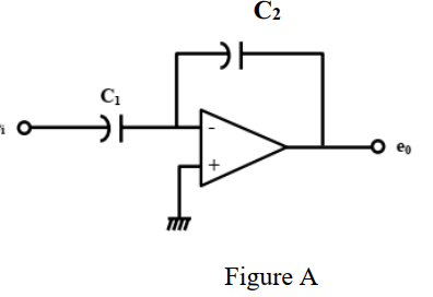
The principle of operation of this meter is based on the determination of the time T that it takes to charge an unknown capacitor C through a known resistor R from 0V to a voltage reference level (Vref) which is determined by a simple voltage divider formed by R1 and R2.. I chose R1 = R2 so that Vref = VCC / 2 making the calculations easier.. VCC for the comparator circuit is provided by the b) R1.Cf is not >> input period. Then you need to allow for R1 and know the frequency if you are calculating the gain. If you are simply making a capacitance meter, and you calibrate the scale with a known capacitor, and keep the frequency constant, then you can ignore their actual values. Op amp IC1 is attached like a comparator, with its (+) input pin attached to R8, which fixes the reference voltage level. Prior to supplying power to the capacitance meter circuit, use a fine screwdriver to adjust the meter M1 needle precisely to the zero level. Position an accurately known capacitor around 0.5 and 1.0 µF at +/-5%. This
capacitance measurement circuit Circuit Diagram
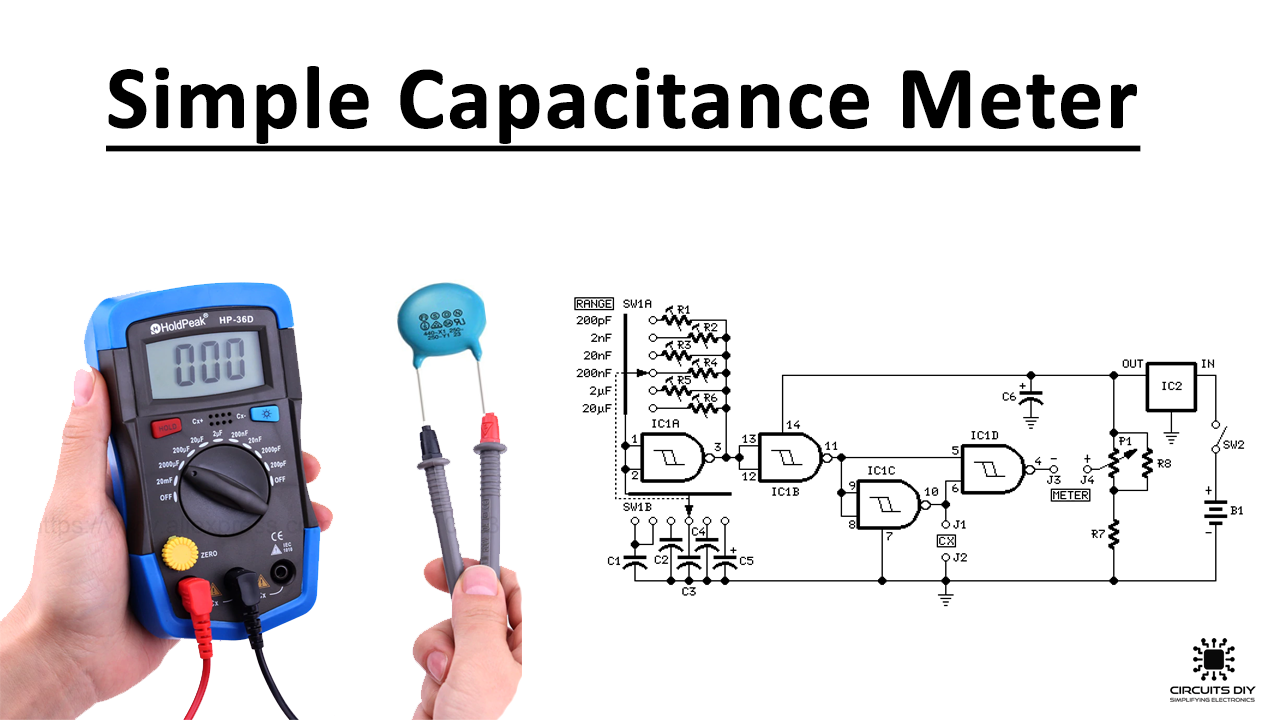
The following capacitance meter circuit includes 4 ranges using full scale values of 5nF, 50nF, 500nF and 5µF, which allows it to be employed for testing a large number of capacitors. The miller integrator is built around a standard operational amplifier type that is designed using IC2. The fundamental working of the circuit is to present Op amp IC1 is attached like a comparator, with its (+) input pin attached to R8, which fixes the reference voltage level. Prior to supplying power to the capacitance meter circuit, use a fine screwdriver to adjust the meter M1 needle precisely to the zero level. Position an accurately known capacitor around 0.5 and 1.0 µF at +/-5%. This Switch ON the power supply - select a suitable position on S1 so that the deflection on the meter reads near about full scale. Fine tune VR1 to make the reading exactly full scale. Due to a linear behavior of the circuit, the readings will perfectly respond to other values of capacitors proportionately throughout the entire meter calibration.
